

RECTIFIER AND CONVERTER PROJECTS


Having a reliable power supply implemented by highly efficient rectifiers and converters minimizes operational costs. With us, you get the best team and equipment you can absolutely trust for big projects with high reliability. Our success derives from the ability to develop highly customized integrated solutions through our Marketing and Manufacturing model based on the Integration Coefficient IC that can match our customers’ most demanding specifications. We can help to design and build rectifier and converter solutions with the highest quality standards. Our extensive industry experience, already explained in OUR VALUE OFFER section, enables us to understand your specific requirements. We provide a DC power supply that keeps your DC critical loads running smoothly and enhances productivity.
State-of-the-art technologies like well-proven SCR (thyristor) and High Frequency Rectifiers and Converters with different AC-DC voltage-current combinations, with robust and reliable design, demonstrate our market-leading position as Supplier for Special Projects and our thorough understanding as consultants of this DC Power-Backup market segment.
The key factors we found to adapt ourselves to any inquiry were simply:
-
Using both technologies (SCR and HF) without diminishing one over the other.
-
Setting up the “modularity” concept, where solutions are developed by connecting pre-designed and pre-assembled unit sections to get the whole equipment/solution.
-
And looking for agreements with the factories that are leading OEM-ODM manufacturing processes with the most recognized brand-names in worldwide rectifier/converter industry that have a big interest in our project after checking for our innovative and unique marketing concept.
The focus of our expertise and experience is on helping you design complete rectifier systems. We take care of all aspects of planning, manufacturing integration, logistic shipments, installation, and end-user manuals, as well as the unified warranty of the whole system based on the knowledge acquired by executing many similar projects in several countries.
Although the cost of the DC Power Supply is minor compared to the total DC equipment investment, a loss of power can result in tremendous production chaos. Our solutions offer you updated technology that minimizes risks, provides total system integration, and ensures a high return on investment. Also, the safety of personnel (approvals) is a high priority for all our systems. With our rectifiers and converters proposals, you achieve the lowest total cost of ownership and boost your production through maximized availability, minimized losses and maintenance, highest personnel safety, longest lifetime, and global presence for service.
We help you to design the power supply properly, and then you enjoy the benefit. We save you the stress of dealing with several suppliers at the same time to get the power supply system to achieve the required performance. We take care of both power quality and performance. Please Contact Us for any need. Also, to make the selection of the solution you may need, we have prepared the following sections where you (just clicking on any of them) will find detailed explanations about all our solutions' availability:
AC-DC RECTIFIERS (BATTERY CHARGERS) MAIN TYPES
SCR AC-DC Rectifiers
High Frequency AC-DC Rectifiers
SCR vs High Frequency AC-DC Rectifiers
SCR AC-DC RECTIFIERS BATTERY-CHARGER SOLUTIONS
Heavy Duty, Automatic Boost-Float, Single Phase, Portable
High Reliability, Single or 3-Phase, Non-Redundant (NR) Series
High Reliability, Single or 3-Phase, Redundant (R) Series
High Reliability, Single or 3-Phase, Special Customized Design
HIGH FREQUENCY (HF) AC-DC RECTIFIERS BATTERY-CHARGERS SOLUTIONS CUSTOMIZED DESIGN
48VDC-30ADC, Single Phase, Hot-Swappable Modules, Special Rack-Mounted
48VDC-50ADC, Single or 3-Phase, Hot-Swappable Modules, Bigger Power Rack-Mounted
HIGH FREQUENCY (HF) DC-DC CONVERTERS CUSTOMIZED DESIGN SOLUTIONS
48VDC-24(12)VDC-50ADC Hot-Swappable Modules, Special Rack-Mounted
CUSTOMIZED CABINETS DESIGN, HIGH FREQUENCY, AND HIGHER POWER AC-DC RECTIFIER-BATTERY CHARGER
The Importance of Quality for Rectifier Cabinets
Main Parts (Sections) of the Rectifier Cabinets
3-Phase AC In, 48VDC-2000ADC Out, Full Features
3-Phase AC In, 125VDC-160ADC Out, Full Features
3-Phase AC In, 600VDC-400ADC Out, Full Features
AC-DC RECTIFIERS (BATTERY CHARGERS) MAIN TYPES
Battery charging is a complex electric-chemical process, in which the discharged electric energy must be replenished from the electric AC network. The quality of the charging process is critical to the health and longevity of batteries. As a result, battery chargers play a key role in the life and performance of today’s industrial batteries.
A battery charger is an electrical/electronic device that converts the incoming AC line voltage into a regulated DC voltage to meet the charging needs of the respective battery. Today’s industrial battery charging market is broadly dominated by SCR-type chargers, which have been in existence for many years, but lately, High Frequency (HF) battery charging technology is making headway into the industrial battery charger market. This is due to the higher efficiencies and smaller sizes and weights that a high-frequency charger offers over SCR types.
SCR AC-DC Rectifiers

SCR battery chargers use SCRs (Silicon Controlled Rectifiers) along with conventional transformers to regulate the charger output. Since the SCR switching action is controlled, SCRs provide more precise control of output voltage and can be easily interfaced with a microprocessor to implement various charging profiles. Furthermore, SCR chargers are less sensitive to line frequency variations (like Ferro-Resonant charger types that are now used much less as new SCR technology is improving and is not recommended in most critical applications) and work well with all types of batteries, including sealed types.
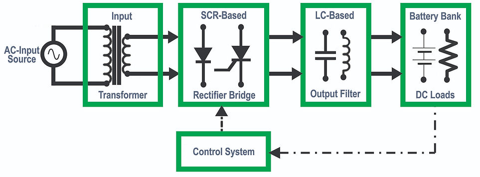
One of the “limitations” of SCR controlled chargers is that they generate un-smoothed DC voltages resulting in higher ripple voltages and consequently higher ripple currents. These currents can cause additional battery heating, especially at high charge rates (e.g., fast charging). However, new designs are adding special LC output filters to decrease this disadvantage significantly, providing very low ripple voltages and currents.
SCR chargers operate at line frequencies (50/60Hz) and use a low-frequency transformer for isolation and voltage step-down, and thus are bulky and heavy. By using rectification techniques based on controlled SCR (basically diodes), the amount of SCR elements used in the rectification process will determine how much the input power factor and current THD input will be, but with better results in the power quality point of view, when more than 12-pulses (instead of standard 6-pulses) input AC rectification techniques are used.
So, SCR rectifiers are variable voltage DC power supplies that are low-frequency, “significant” amplitude ripple systems. Their main advantages are that these systems are rugged and have a history of durability in the market, with a number of worldwide customers having systems running after 40 or 50 years. They regulate and react steadily, carry a lot of power in big copper winding, and are fairly easy to troubleshoot with large, easy-to-identify components.
High Frequency (HF) AC-DC Rectifiers

A High Frequency AC-DC Rectifier-Battery Charger is a class of power supplies that incorporates fully controllable switching power devices, e.g., MOSFETs and IGBTs, and can thus operate at frequencies much higher than line frequencies (few kHz to 100’s of kHz). Unlike SCRs, which are half-controlled devices with uncontrollable turn-off, MOSFETs and IGBTs can be fully turned on and off at any instant in time, allowing for precise control of the charger output.

A typical High Frequency Rectifier-Battery Charger incorporates a front-end AC-DC rectifier to generate an un-regulated DC input voltage, a high frequency (HF) power converter that converts input DC input a high frequency AC voltage, a high frequency isolation transformer to provide output isolation as well as voltage step-down function, and an output rectifier and filtering stage to generate a smooth, very low ripple output DC voltage. Pulse Width Modulation (PWM) or Maximum Power Point Tracking (MPPT) techniques are the main ones generally employed to regulate the charger output, where the duty cycle of the switching power device (ratio of on-time to switching time) is controlled to guarantee the maximum output current and to keep the output DC voltage of the charger.
The main advantage of High Frequency Rectifier-Battery Chargers over SCR technology is the significant size and weight reduction of the isolation transformer and the subsequent improvement in energy transformation efficiency. Note that the size of an isolation transformer is inversely proportional to the operating frequency, i.e., the higher the operating frequency, the lower the transformer size. For example, a high-frequency transformer operating at 60kHz is ideally 10,000 times smaller than a low-frequency 60Hz transformer and is much more efficient.
However, the High Frequency AC-DC Rectifier is the relatively new kid on the block. Switch-modes are an electronic power supply that uses a switch from AC to DC, back to AC, then once again back to DC. This is all done at high frequency, allowing for the internal parts to be smaller. They utilize a high primary voltage, where typical 480VAC input units typically see 700VDC switching voltages inside the transformer. This makes failure a bit more destructive and violent due to smoke generation. But with smaller parts, tighter winding, smaller footprints, and an even tinier tolerance, these precision pieces of equipment offer great space efficiency per watt, modern computer interfaces, and intuitive controls. Switch-modes have been around for roughly 40 years. Traditionally, they were used in smaller current applications, and it wasn’t until 15-20 years ago that large-scale switch-modes were successfully deployed.
SCR vs High Frequency AC-DC Rectifiers

After explaining each type of rectifier deeply, we’d like to dispel a popular myth regarding HF vs SCR chargers:
Neither type of unit is better than the other. Both HF and SCRs perform almost identically well in electronic regulation, and technology and manufacturing techniques have allowed them to perform at a similar level of process performance.
HF and SCRs rectifiers can both regularly regulate to the 1000th of a volt and even more; there is absolutely zero difference between them in their ability to withstand exposure to hard environments.
Essentially, HF units take up less real estate, consume less cooling resources, and tend to, on average, perform the full range of operation at a higher electrical efficiency than SCR rectifiers. The lower you turn a SCR rectifier in voltage, the higher the chance the machine will not convert AC to DC as efficiently as the same rated, competing switch-mode. When you increase the voltage in an SCR rectifier, it has a better chance of performing more efficiently than the same rated, performing switch-modes.
Furthermore, because it takes more switch-mode units to match the regular output amperage of an SCR, you now have more points of potential failure, but because of the space savings provided by HF units, you can solve this issue by implementing redundancy (N+1, N+X, or others) techniques that will guarantee the longest time operation without failure of the total system. SCR units can also be connected for redundancy operation, but the installation processes to get reliability have been more cumbersome and expensive, with a lot more space needed for the total system.

On the other hand, one thing that customers should be aware of when it comes to HF units is the learning curve involved with these systems. The equipment is much smaller and has tighter arc paths with larger voltage potentials inside. The opportunity for a breakdown is different, and the equipment follows a different Preventive Maintenance path to keep it running. It is similar to how the maintenance on your sports car is different from the maintenance on your trusty diesel pickup truck. If your rectifier manufacturer forces you to carry a whole module rather than just the parts needed to fix a bad module, then this trend may not be true. It has nothing to do with one being better than the other; they are just different tools to consider in your arsenal
HF vs SCR rectifiers have very different resource requirements. SCRs are more resource hungry both in footprint and real estate. SCR rectifiers require strong weight-supporting platforms and wide installation spaces. Air-cooled SCR rectifiers require room for forced air cooling to escape. Water-cooling SCR rectifiers require discharge to be treated as waste. Sometimes, the production real estate becomes expensive to support. There is no single point of access, so you need to be able to get three different angles to perform maintenance work on an SCR unit. If you can’t get into it, you can’t fix it if it breaks. You will need at least two feet around the unit so there is enough space for a technician to perform maintenance checks and complete repairs.
SCR parts are large, heavy, and costly. The parts used in SCR rectifiers are subject to long lead times and market trends. HF parts are smaller, easier to store due to their size, but also easier to misplace. It is typically easier to have spare switch-mode parts on your shelves due to their overall lower price and material cost. Switch-mode runs at a higher frequency, allowing a tighter configuration and smaller weight while delivering the same overall power as an SCR rectifier. Those smaller components tend to fail more frequently due to relative size when exposed to corrosive environments or moisture than the larger SCR componentry. So, for controlled temperature and humidity environments, using HF units could be the best option, but for most heavy industrial applications SCR type is still the way to go.
It does mean that the rate at which both SCR and HF rectifiers break down is much more dependent on environmental factors rather than on how the rectifier is used or the time that the machine is exposed to the environment. In fact, more than 90% of rectifier repairs are based on environmental abuse instead of equipment misuse, such as rack crashes, improper set-points, or corrosive exposure.
SCR AC-DC RECTIFIERS
BATTERY-CHARGER SOLUTIONS
Heavy Duty, Automatic Boost-Float, Single Phase, Portable

High reliability, heavy duty, simple design, portable (meaning that can be used and moved to any place by using wheels), very affordable cost, AC input cable and DC output cables included with DC connector, automatic operation, just floating and boost voltage adjustable, DC Volt and Amp meters, single phase Input 120V or 208/220V or 230/240V input and the following models:
-
12V: 30, 50, 80, 120, 150 Amps
-
24V: 30, 50, 80 Amps
-
48V: 10, 20, 40 Amps
Features & Benefits
-
Affordable price.
-
Portable and On-board models.
-
Simple automatic operation.
-
Automatic, microprocessor, SCR design.
-
Charge flooded and sealed batteries with one charger.
-
Protect batteries from under-charge and over-charge.
-
Protect batteries from over-temperature.
-
Switches to float mode when the charge is complete.
-
Soft-start reduces inrush current and noise on AC lines.
-
Self-adapting single-phase AC input (taps) for domestic and international markets.
-
Finish charge at constant voltage.
-
Soft-start and maintained float mode.
-
LED indicators for charge status and fault conditions.
-
DC Voltmeter and Ammeter.
-
Floating and Boost Voltage adjustment by front access potentiometers.
High Reliability, Single or 3-Phase, Non-Redundant (NR) Series

The NR Series is a new kind of special SCR AC-DC Rectifier-Battery Charger. These units adopt the digital IC; the control trigger has good integration, powerful functions, and extreme reliability. The charger has functions such as constant-current and/or constant-voltage, as the power for the formation and maintenance of the battery. The charger can be operated automatically if it is used with a micro-PC. Available in single and three-phase AC input, from 12 to 400VDC and up to 1500ADC output, and using ultra-rugged phase-controlled technologies, this series is ideal for all industrial applications.
The NR Series applies the latest digital control technology to “manage” the 6-pulse SCR bridge rectifier. The embedded micro-computer processes signals up to 10 times faster than standard analogue methods. The product design affords easy front-access to all vital modules of the system. The memory function starts the machine automatically after the utility power is restored. The charging method and processes switch automatically.

Features & Benefits
-
Rugged phase-controlled thyristor technology
-
12VDC to 600VDC; 16 ADC to 1500 ADC
-
Single and 3-phase models.
-
Versatile constant-voltage and constant-current charging modes
-
Large LCD Display, user programmable
-
Wide adjusted voltage and current range
-
Battery management system
-
Programmable charge voltage/current limit
-
Precise adjustable temperature compensation
-
Isolated RS232 or RS485, Ethernet
-
Robust mechanical design
-
Up to IP65 external protection
-
Access facility software
-
Full data logging
-
Multiple protection
High Reliability, Single or 3-Phase, Redundant (R) Series

The R Series redundant SCR rectifier is a new type of SCR charger for battery. This charging system is made by two independent charging loops in parallel into the same cabinet, saving installation space costs and carrying out the redundancy charge function, increasing reliability for those projects where downtime is more than critical.
This system is controlled by digital intelligent with multi-charge mode, simple operation and reliability, there is not sequence requirement. Independent AC inputs let you connect every loop of the charger to different sub-stations increasing reliability. The transformers are made by high strength paint cooper, which can achieve H grade high temperature resistance and isolation. The power units are made of aluminum profiles with great heat conductivity and high-power disc-type thyristor units, enough to guarantee the longest life span.
Same as the NR Series, these units are available in single and three-phase AC input, from 12 to 400VDC and up to 1500ADC output, and using ultra-rugged phase-controlled technologies, this series is ideal for all industrial applications and also applies the latest digital control technology to “manage” the 6-pulse SCR bridge rectifier. The embedded microcomputer processes signals up to 10 times faster than standard analogue methods. The product design affords easy front-access to all vital modules of the system. The memory function starts the machine automatically after the utility power is restored. The charging method and processes switch automatically.
Redundant, independent charger modules increase reliability as a malfunction of one of them does not disable the charging system; the remaining module continues to operate at full capacity. There are fewer single points of failure for the system. R Series provides lasting secure power architecture for your industrial application design: natural ventilation on most of the range; continuous operation at full load in a permanent 40 Celsius degrees ambient temperature; system lifetime of more than 20 years in continuous operation conditions, robust mechanical and horizontal acceleration stress up to 0.5g as standard. Over-current, over-voltage, over-temperature, phase sequence detecting and phase lost protections.

Features & Benefits
-
Double Charger Modular, same cabinets
-
12VDC to 600VDC; 16 ADC to 1500 ADC
-
Single and 3-phase models.
-
Parallel/Redundant work mode
-
More reliability and flexibility
-
Rugged phase-controlled thyristor technology
-
Versatile constant voltage and constant current charging modes
-
Large/Double LCD/programmable display
-
Wide adjusted voltage and current range
-
Battery Management System
-
Programmable charge voltage/current limit
-
Precise adjustable temperature compensation
-
Isolated RS232 or RS485, Ethernet
-
Robust mechanical design
-
Up to IP65 external protection
-
Access facility software
-
Full data logging
-
Multiple protection
High Reliability, Single or 3-Phase, Special Customized Design

Both the NR and R Series are fully adaptable to customers' power backup needs. A full range of additional options is available to tailor solutions for diverse industrial environments:
-
12-pulse SCR full-bridge rectifiers.
-
Fast-acting fuses.
-
Several bypass operation options in both the AC and DC sides.
-
Dropper Diodes to lower the DC output voltage when chargers are in boost mode.
-
Low Battery Disconnect.
-
High Battery Disconnect.
-
AC and DC customized Surge Protection Devices.
-
Isolated Redundancy: Using separated units controlled by a “transfer cabinet” let users to charge batteries and supply DC power to DC Loads transferring the power from one charger to other when one unit may fail or when maintenance is needed, also letting customers to have the possibility to “move” units to supply power to other loads according to their needs for maximum flexibility. More and more customers are asking for this kind of solution as single units are becoming more reliable when technology is improving.
-
Output LC filter for battery eliminator, typically used when rectifiers are just used to supply power to DC loads, and no batteries are involved in the solution.
-
Diverse networking communication options, such as TCP/IP-SNMP, DPN3, IEC61850, and others by using special protocol converter devices.
-
Special NEMA or IP cabinet protection.
-
Special painting colors and anti-corrosive treatments.
-
Special cabinet dimensions.
-
Upper or lower cable access.
-
Special packaging for shipping.
-
Special DC, AC, and voltage combination designs.
Typical Block Diagram for Isolated Redundancy and extra protections

HIGH FREQUENCY (HF) AC-DC RECTIFIERS BATTERY-CHARGERS SOLUTIONS CUSTOMIZED DESIGN

The power supply of any telecom or industrial system forms the link between the national power AC supply (mains) and the DC loads or communication system itself. Therefore, not only must it be matched to the parameters of the mains, but also fulfill the requirements of the system to be backed up and of the energy stores (batteries). This is achieved by transforming the voltage of the mains or standby power supply system, taking into consideration such requirements as magnitude, tolerance, purity, etc.
Our group has developed OEM-ODM agreements with recognized suppliers in Asia to provide customized, best quality proven High Frequency Rectifiers mainly in 24, 48, 110-125, and 220-240VDC volts. Here you will find some examples of the main units and configurations available for most applications in this area. It is mainly used in power plants, hydro-power stations, various substations, switch-gears, and user substations, electric power, petroleum, chemical industry, metallurgy, machinery, paper making, building materials, textile, wine making, and other fields.
48VDC-30ADC, Single Phase, Hot-Swappable Modules, Rack-Mounted

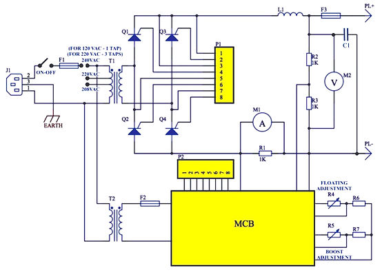
Operating Principle
AC power is first input to the AC-INPUT MCB and then fed into the rectifier module after lightning protection and filtering. AC-INPUT acts as protection to over load and short circuit to the AC power. The user’s battery is connected to the DC output side through MCB BAT, and the circuit breaker provides disconnection control, over-load and short-circuit protection to the battery.
Normally, the monitoring module controls parameters for the rectifier module and power distribution unit. The system operates according to preset parameters or user commands. If the mains supply fails, the system switches to the battery for power supply. When the battery discharges electricity until its voltage falls below the low-voltage alarm threshold of 46V (configurable) for the upper device, the monitoring module reports an alarm message and turns off the output load. The system stops working. When the mains supply resumes, the system returns to normal (you can reconfigure the above default monitoring data). The system provides a reduced power rate when the operating temperature reaches 55 Celsius degrees or above.
Additionally, the maximum power is obtained when the input AC voltage is under -20% to +30% range approximately, but the system is provided with a “fuzzy range” feature, letting you work for extended input AC voltages with less output power, keeping the same features and protections.
Our 48V embedded rack-mounted modular hot-swappable 48VDC-30ADC modules power system consists of the AC-DC power distribution frame (can be user customized), monitoring module, and rectifier modules, with functions of AC-DC lightning proof and DC power distribution. The monitoring module supports outside signal input, communication transformation, AC/DC detection, and contactor control. The whole system is of high reliability and performance, and can be operated through PC software.
Features & Benefits
-
Powered by the compensation technology, the rectifier module provides a power factor of up to 0.99.
-
The range of operating AC input voltage is extended to 90-290V. Options for different AC inputs as needed.
-
Using the full-bridge soft switch Zero current/voltage switching technology, the rectifier module delivers efficiency up to 92%.
-
Operating temperature range: -25°C~+55°C
-
Powerful battery management: Load power-off and low-voltage protection (LVLD+LVBD) and secondary power-off; temperature compensation, automatic even and float charging management; automatic voltage adjustment; power capacity calculation; online battery testing, etc.
-
Non-intrusive hot swapping shortens the time for rectifier module replacement to less than one minute.
-
Supports flexible networking through various communication ports (e.g., RS485 and dry contact) to enable local and remote monitoring without human intervention.
-
Mature AC/DC lightning protection, making it suitable for use in thunder-prone areas.
-
A complete set of fault protection and alarm features.
-
Front access servicing supports space-efficient wall mounting.
-
Ultra-low radiation: Based on a cutting-edge EMC design, the rectifier module fully complies with the requirements specified in Limits and Methods of Measurement of Electromagnetic Compatibility for Telecommunication Power Supply Equipment YD/T983).
-
Safe and reliable: compliant with EN60950 and GB4943.
Configuration
Our standard embedded systems are available in the following models and configurations from 30Amp to 120Amp – N+1 Redundancy, then 60Amp to 150Amp- as shown in the following table. (Models and configurations may vary for non-standard customized products.


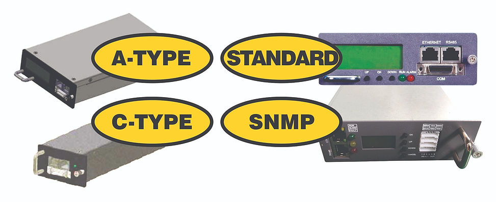
Monitoring Module Function
Powerful in detection and control, monitoring modules can detect the working status of the power system in real time and controlling work status of the rectifier module based on parameters. Through battery pack maintenance and management, these modules enable the embedded power system to operate safely and reliably. The modules also raise alarms when the rectifier module does not function properly. Monitoring modules communicate with upper devices over a user-defined protocol through the RS485 interface and report detected values to upper devices to facilitate central management. The modules can be queried, configured, and controlled by upper devices. Options for TCP/IP-SNMP network protocol communications and others are available upon request.
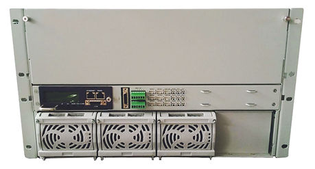
48VDC-50ADC, Single or 3-Phase, Hot-Swappable Modules, Bigger Power Rack-Mounted

Same as the above models, this embedded Power System is an AC-DC Rectifier product mainly applied in the telecom field, such as mobile communication, satellite communication ground station, microwave communication, programmable controlled exchanger, etc. Power system consists of cabinet power distribution, rectifier module (at least one), and monitoring module physically and smartly distributed in 6U to 12-15 or 18U rack-mounted cabinet and using 50ADC module capacity in 48VDC with single phase or three phase AC input. This system has stable performance, practicality, and is specially designed for bigger power systems with local monitoring and back-office operations software that can be easily integrated with a man-machine interface.
Operating Principle
-
Unipolar power lightning protection system against lightning or high surge damage in AC mode is provided.
-
AC power distribution, single or 3-phase AC input, achieves related protection promptly.
-
Single-phase voltage is balanced distribute to the corresponding rectifier.
-
Rectifier working in a parallel converter converts AC power to DC power through the copper bar connected to a DC power distribution, supplies DC power for DC load, and charging for battery.
-
According to the customer’s need, rectifier modules and rack quantities can be selected freely.
-
DC distribution provides output power to the device and charges the battery, provides load and battery’s disconnect work.
-
Providing two-way battery interfaces and multi-way load interfaces (load interface can be configured randomly according to the user’s demand).
-
When the mains fails, the battery provides power for the device. When the battery’s voltage is low to the setting detached value of LVD disconnect (LVD detached value is 43.2V, recovery value is 50V), LVD disconnects from the load, the controller will beep an alarm, send an alarm to the host computer or a remote control center, and disconnect the battery to prevent excessive battery discharging.
-
The output DC lightning function design will achieve an outstanding anti-surge function.
Features & Benefits
-
The rectifier module adopts active power factor compensation technology, with a power factor up to 0.99.
-
The AC input voltage of the normal operating range is as wide as 90 ~ 280V.
-
Rectifier modules adopt full-bridge soft switching technology, and efficiency can reach above 92%.
-
Perfect battery management: low voltage load disconnect (LVLD) and low voltage battery disconnect (LVBD) to achieve temperature compensation, automatic float control, automatic voltage regulator, battery capacity calculation, and online battery test function.
-
Switching Power Supply for System integration adopts no damage hot insert and pull technology (hot-swappable), replacement time is less than 1 minute.
-
Network design, providing a variety of communication interfaces (for example: RS485, dry contact), flexible networking can achieve local and remote monitoring, unattended. Perfect AC and DC side lightning protection design used in multi thunderstorm area.
-
Complete fault protection, fault alarm function.
-
Comprehensive operation and maintenance, and can be mounted against the wall, saving space effectively.
-
Excellent lightning-proof design applicable to areas with frequent thunderstorms
-
Ultra-low radiation. Adopt advanced electromagnetic compatibility design, the rectifier module can meet requirements for conducted and radiated interference of "the communication power equipment electromagnetic compatibility Limits and methods of measurement " ( People's Republic of China telecommunications industry standard YD/T983).
-
Front panel for operation and maintenance
-
Safe and reliable. System design in full compliance with safety standards EN60950 and GB4943.
-
Power monitoring module has strong detection and control functions, can detect the real-time working status of the power system, control the rectifier module status according to detection parameters to meet maintenance and management requirements of the battery pack, makes power system safe and reliable, and can alarm in the case of rectifier abnormality. Develop the company's own agreement according to the company’s real demand through RS485 method, communicate with the background host computer, accept the host computer’s query, set and control, reported detected physical data to the background host computer for easy centralized management.
-
The controller monitors all real-time data and saves more than 1,000 pieces of alarm information. Controller detects the monitor output voltage, current, automatic cumulative work time, detects AC voltage, current, detection status of each AC air switch, lightning protection module status, each air switch of DC distribution, fuse state, monitoring parameters of each environmental, etc.
-
The monitor controller can control up to 32 modules. Controller monitors the power system to start working in the default parameter status or the parameter status set. The user can set parameters through the controller keyboard or PC background. System running parameters and status can be displayed on the controller's LCD or displayed on the PC background. System can be achieved through remote monitoring through serial port connection or through an optional TCP/IP-SNMP network from a centralized monitoring station. This system can be from a network, working with other power control system devices in other environments conveniently.
-
The controller records the voltage, current, and time of battery charge and discharge, and can judge battery is good or bad according to the curve of battery charge and discharge.
-
The user can monitor and change settings/status through the LCD and keypad on-site.
-
Background monitoring control failure, LCD control function will act as a backup controller to work.
-
The controller sends data to the host computer or remote monitoring center.
-
User can change system settings or status through power monitoring software, remote or local (under remote circumstances, allow up to 255 base stations, can be expanded to 65, 535 base stations).


HIGH FREQUENCY (HF) DC-DC CONVERTERS
CUSTOMIZED DESIGN SOLUTIONS

48VDC-24(12)VDC-50ADC Hot-Swappable Modules, Rack-Mounted

Using the same physical structure for the former 48V-Up to 150Amp AC-DC rectifiers rack-mount models, we also offer the same racks as DC-DC converters from 48VDC to 24 or 12VDC using DC-DC power modules with a nominal 50ADC capacity, but they can also be pre-set from the factory from 10 to 50ADC according to customer needs.
The DC-DC Converter module is designed with a high-frequency pulse width modulation technology, "low self-poor" streaming technology, and highly reliable fast protection technology. "Low self-poor" control unit ensures current sharing between modules, automatic current, light load (5% load), between rated load and maximum current error <2ADC. Highly reliable and rapid protection is specially designed for the features of short circuit to ensure that the module will not get damaged in the long-term, and comprehensive protection features to ensure the safe and reliable operation of the system and modules.
DC-DC Converter Module exchange circuit is a double forward converter circuit topology; the switch is turned on at the same time, the risk of leg straight bridge topology does not exist; the danger caused by bias magnetic saturation of the transformer also does not exist; ensure the module's reliability from the topology. Double forward topology dual complementary octave, so the operating frequency of the rectifier is up to 160kHz.
The units are manufactured following the following standards and basic testing procedures:
-
GB2423.2-89 Basic testing procedures for electrical and electronic products, standard Bd.
-
GB2423.1-89 Basic testing procedures for electric and electronic products, standard Ad.
-
GB3873-83 Communication equipment product packaging General technical requirements.
-
Communication with a high-frequency switching power supply in the network quality certification test experimental rules.
-
YD/T731-2008 Communication with high-frequency switching rectifier.
-
XT-005-95 (Communications Authority (station) power system technology requirements (Temporary Provisions)).


Features & Benefits
-
High-performance, high-reliability power supply/Step Down Converter/Power Supply 48VDC input, 24/12VDC output, Telecommunication Power System.
-
Input: 40V to 66V DC; Output: 20(10) ~ 28(14)VDC.
-
Output Module DC: 10, 20, 30, 40, and 50 Amp. Set up at the factory.
-
Rack-mounted 19” Units from 1U to 3U: 24(12)V-50A (one module) to 24(12)V-250A (five modules).
-
The converter module adopts active power factor compensation technology, with a power factor up to 0.99.
-
DC input voltage of the normal operating range is as wide as 42-58V.
-
Converter modules adopt full-bridge soft switching technology, and efficiency can reach above 92%.
-
Perfect battery/DC load management: low voltage load disconnect (LVLD) and low voltage battery disconnect (LVBD) to achieve temperature compensation, automatic float control, automatic voltage regulator, battery capacity calculation, and online battery test function.
-
The converter module adopts no damage hot insert and pull technology, with a replacement time of less than one min.
-
Network design, providing a variety of communication interfaces (for example: RS232/485, dry contact), flexible networking can achieve local and remote monitoring, unattended.
-
Perfect DC and DC side lightning protection design used in multi thunderstorm area.
-
Complete fault protection, fault alarm function.
-
Comprehensive operation and maintenance, front access, can be mounted against the wall, saving space effectively.
-
Ultra-low radiation. Adopt advanced electromagnetic compatibility design, the rectifier module can meet requirements for conducted and radiated interference of "the communication power equipment electromagnetic compatibility Limits and methods of measurement" (People's Republic of China telecommunications industry standard YD/T983).
-
Safe and reliable. System design in full compliance with safety standards EN60950 and GB4943.
CUSTOMIZED CABINETS DESIGN, HIGH FREQUENCY AND HIGHER POWER AC-DC RECTIFIER-BATTERY CHARGER
The Importance of Quality for Rectifier Cabinets
The real value in long-term care of your equipment starts with a good cabinet. If you can control the environmental exposure while still cooling the equipment properly, you are great. When evaluating any type of rectifier, it’s critical to realize that not all cabinets are created equal. Our experience is offered to the customers to let them share the opportunity to reach High Frequency Rectifier cabinets, where all quality, safety, and economical considerations have already been taken into account to guarantee the best results when building your critical DC system.
Independent of the power requirements, high-frequency transistor-controlled rectifiers, also called modular switching-mode power supplies, batteries, AC-DC distribution systems, and optional protections, as well as display monitoring systems and light indicators, are combined in very precisely designed cabinets to form a “compact power supply system” which is usually installed near the switching equipment it powers. The combination of all elements is not only done under physical, heat management, and environment control points of view, but also under economic considerations with the best high benefit/cost ratio to produce a compact and reliable power supply system.

Main Parts (Sections) of the Rectifier Cabinets
Basically, all cabinets we can provide for the most demanding projects are composed of the following items:
AC power distribution input
The AC system of the power cabinet provides AC power for the high-frequency switch rectifier module section and is usually protected with an AC Surge Protective Device (SPD).
High-frequency switch rectifier module
The high-frequency switch rectifier module section is the heart of the power cabinet. It is responsible for charging the battery, and, on the other hand, it supplies the normal working current to the DC loads. There is a monitoring board inside the charging module to monitor and control the operation of the module. Since the charging module itself has a CPU, the charging module can also operate independently from the monitoring module. A DC SPD is commonly provided to protect the DC bus-bar.
DC power distribution output
The DC system of the power cabinet provides DC power for the DC loads and battery bank section and is usually protected with a DC Surge Protective Device (SPD).
Monitoring system module
The monitoring system of the power cabinet is a man-machine interface with an LCD. It is the bridge between the bottom module and the background management. It is the brain of the power cabinet. It is responsible for managing the charging modules and the power delivered to the DC loads, fault information, historical information records, and other various parameters.
Insulation detection module
It is used to monitor the DC system voltage and its insulation. When the DC system has a decrease in insulation strength (220V DC voltage system is generally less than 25KΩ, 110V DC voltage system is generally less than 7KΩ, just as examples), a sound and light alarm is issued, and can find the corresponding branch number and resistance value can be found.
Voltage regulator Dropping Diode chain module.
When the DC power supply system balances the battery pack (boost charging mode), the output voltage of the charging module will be higher than the rated voltage value of the control circuit. At this time, a voltage regulator is needed to regulate the voltage to supply power to the control mother circuit. The Dropping Diode chain module is such a voltage regulating device, which can automatically and manually change the voltage provided to the DC loads then ensuring that the voltage of the DC-Load bus-bar is within the range. This device uses the P-N junction of the high-power rectifier diode to superimpose the forward voltage drop to generate the adjusted voltage drop. This method is reliable, impact resistant and easy to maintain.
Battery Bank
As the backup power supply of the DC system of the whole station, when the charging module stops working, the battery continuously supplies power to the DC-Load bus-bar. It is equivalent to a storage mechanism, which is the warehouse of the entire power cabinet. Everyone knows that AC power cannot be stored. Therefore, the power cabinet uses the battery bank to convert the DC power converted by the charging modules into chemical energy and then converted into electrical energy to power the DC loads. In the OEM Battery Projects section of this website, you will find the best option to pair the rectifier technology chosen with the right battery technology.


Dropped Diode set
It reduces the output voltage of the rectifier and stabilize it at a certain fixed value when in boost or equalization charging and it has a better system efficiency with high reverse leakage current.
Operation
During normal operation when batteries are in float, the contactor is closed and output drop diodes are shorted. During boost or equalize charge, the contactor is open and a voltage drop over the diodes is maintained according to the customer’s specification.
During boost or equalize charge, all load current is flowing through the drop diodes and creates a power loss, which will generate heat.
Depending upon load output and design of voltage drop over the diodes, this power loss can exceed several kW.
The design of such a system incorporates heat dissipation, additional power from the rectifier for power loss over drop diodes and bulky drop diodes mounted on cooling plates.

Below are some examples of configurations or special projects fully adapted to specific applications of 48V, 110V, 220V, and 600V DC rectifiers.
3-Phase AC Input, 48VDC-2000ADC Output, Full Features

3-Phase AC Input, 125VDC-160ADC Output, Full Features


3-Phase AC Input, 600VDC-400ADC Output, Full Features
